I've always dreamt of getting some kind of output from my RISC-V core. I mean, it is a CPU, right? It should be able to do something. Therefore, I decided to add some basic features that will allow me to get UART output from my RISC-V core! This way, I can get it to print messages like "Hello, World!" or even more complex stuff.
I started by having a look at everything required to achieve this. I needed to add some Control and Status Registers (CSRs) to my RISC-V core, which would allow me to control the UART peripheral. I also needed to implement interrupts, so that I could handle incoming data from the UART. Finally, I needed to add a timer, so that I could generate periodic interrupts for tasks like updating the system clock or handling timeouts.
Adding CSRs
To add CSRs to my RISC-V core, I decided to target the Machine mode CSRs, which are used for low-level control of the CPU. These are nothing but registers that can be read and written to by the CPU using special instructions. I added a few CSRs to my core, including:
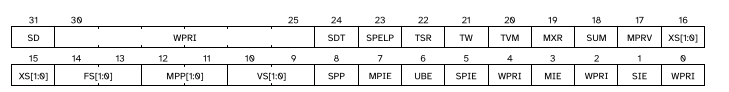
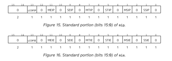
mstatus: Machine status register, which holds the current state of the CPU.misa: Machine ISA register, which indicates the supported instruction set architecture.mie: Machine interrupt enable register, which controls which interrupts are enabled.mtvec: Machine trap vector register, which holds the address of the trap handler.mscratch: Machine scratch register, which can be used for temporary storage.mepc: Machine exception program counter, which holds the address of the instruction that caused an exception.mcause: Machine cause register, which indicates the reason for the last exception or interrupt.mtval: Machine trap value register, which holds additional information about the last exception or interrupt.mip: Machine interrupt pending register, which indicates which interrupts are currently pending.cycle_counter: A counter that increments with each clock cycle, useful for timing operations.
The info about these CSRs can be found in the RISC-V privileged specification. There are a lot more CSRs available, like mvendorid, marchid, mimpid, etc., but I decided to start with these basic ones.
A lot goes into the data held in these CSRs, like the current privilege level, whether interrupts are enabled, etc. For example, the mstatus register holds the current privilege level, endianness, memory access permissions, etc. The manual provides much more detail on how these registers work and what each bit means.
Next, there were a few instructions that I needed to implement to read and write these CSRs. The most important ones were:
csrrw: Read and write a CSR.csrrs: Read a CSR and set bits.csrrc: Read a CSR and clear bits.
..and their variants for reading and writing the CSRs. I found this website which provides a great overview of the RISC-V instructions: Luplab's RISC-V Instruction Encoder/Decoder. It helped me understand how to encode and decode the instructions for reading and writing the CSRs, and it comes with a handy instruction set reference which explains exactly how an instruction works and how it would look in some form of pseudo-hardware description language (not sure what to call it, but it looks Verilog-ish). Some of these instructions were "atomic" instructions, which meant that they needed to be implemented in a way that ensured that no other instruction could interrupt them while they were executing. This was easy to implement since nothing could disturb my pipeline once an instruction was in the execute stage.
The Machine mode comes with a little more instructions, like mret, which is used to return from a trap or interrupt handler, and ecall, which is used to make a system call. These instructions are used to handle exceptions and interrupts, and they require a little more work to implement, adding a new module for interrupt handling and exception handling.
if (mie_global) begin
    // Priority: External > Timer > Software
    if (meip && meie) begin
        interrupt_pending = 1'b1;
        interrupt_cause = MACHINE_EXTERNAL_INTERRUPT; //32'h0000000B;
    end else if (mtip && mtie) begin
        interrupt_pending = 1'b1;
        interrupt_cause = MACHINE_TIMER_INTERRUPT;
    end else if (msip && msie) begin
        interrupt_pending = 1'b1;
        interrupt_cause = MACHINE_SOFTWARE_INTERRUPT;
    end
end
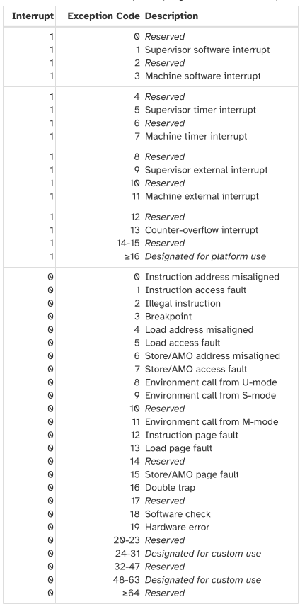
The mcause CSR is used to indicate the reason for the last exception or interrupt, and it is set by the CPU when an exception or interrupt occurs.
What goes into handling an interrupt:
- Check if interrupts are enabled (
mie_global). - Check if any of the interrupts are pending (
meip,mtip,msip). - Set the
interrupt_pendingflag andinterrupt_causebased on the highest priority interrupt that is pending, which is then written to themcauseCSR. - Set the
mepcCSR to the address of the instruction that caused the interrupt. - Set the
mstatusCSR to indicate that an interrupt is pending - Set the
mipCSR to indicate which interrupts are currently pending.
Adding Timer
I needed a timer to generate periodic interrupts for tasks like updating the system clock or handling timeouts. The timer comes with mtime and mtimecmp CSRs, which are used to hold the current time and the time at which the next interrupt should occur, respectively. These interrupts are only taken if interrupts are enabled and the mtie CSR is set.
The specification gives reasoning as to why mtime is a memory-mapped CSR, which means that it can be accessed like a memory location, and it is not a register that can be read or written to directly.
Accurate real-time clocks (RTCs) are relatively expensive to provide (requiring a crystal or MEMS oscillator) and have to run even when the rest of system is powered down, and so there is usually only one in a system located in a different frequency/voltage domain from the processors. Hence, the RTC must be shared by all the harts in a system and accesses to the RTC will potentially incur the penalty of a voltage-level-shifter and clock-domain crossing. It is thus more natural to expose
mtimeas a memory-mapped register than as a CSR.
UART Output
To get UART output, I needed to add a UART peripheral to my RISC-V core. This peripheral had control registers that could be accessed via memory-mapped I/O. It had a data register for sending and receiving data, a control register for enabling and disabling the UART, and a status register for checking if the UART is ready to send or receive data, and a baud rate register for setting the baud rate of the UART.
Baud rate was a tricky concept for me, since while writing testbenches I kept messing up the timing of the UART signals. The baud rate is the number of bits per second that the UART can transmit, and it is usually set to a standard value like 9600, 115200, etc. The register held values that could be used to calculate the baud rate based on the clock frequency of the system. For a 50MHz clock, a baud rate of 115200 would require a divisor of 434.78, rounded to 435. This means that the UART would transmit one bit every 435 clock cycles.
I only ended up implementing the transmit functionality of the UART, which means that I can send data to the UART, but I cannot receive data from it. Hopefully one of my club-mates will implement the Rx functionality.
Testing the entire thing
I turned to the trusted cocotb for testing the new features I added to my RISC-V core. I extended the previous testbenches for the decoder and alu for handling the new instructions, making sure that the new test vectors are compiled with the -march=rv32i_zicsr_zifencei flag to enable the new instructions.
A neat UartMonitor class was handy for accepting UART data and decoding it. However, I ran into an issue when I was using the shared clock to read the UART data. This seems to be common for cocotb, where I need to utilize Timer to read certain signals properly.
At this point, the design was large enough for iverilog to throw a fit and take a long time to compile. I had to switch to verilator for simulation, which was a bit of a pain since there seems to be a bug in cocotb-test that prevents generation of waveforms for debug. I hope someone fixes this or I do, because all of the testbenches rely on cocotb-test and it would be really tough making Makefiles for the traditonal cocotb testing.
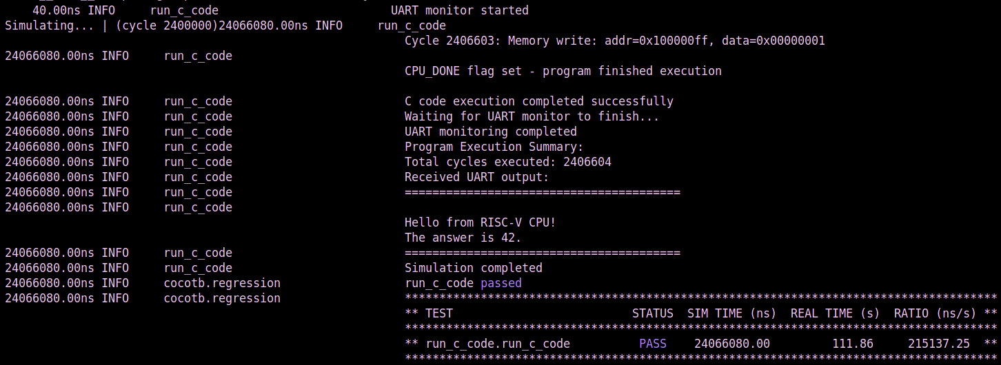
I also created a small script that takes in any C file and compiles it to a RISC-V binary, and then runs it on the core. With this, came some really fun programs that I could run on my CPU, and as you know a programmer must greet the world before doing anything else.
int main() {
    uart_init();

    uart_puts("Hello from RISC-V CPU!\r\n");
    uart_puts("The answer is 42.\r\n");

    write_reg(CPU_DONE_ADDR, 1);

    while (1) {
        asm volatile("nop");
    }

    return 0;
}
And with that, my CPU can answer the age-old question of life, the universe, and everything.
I also went a little over the board while trying to implement more things like print numbers, but found out my CPU sorely misses the mul and div instructions.
Conclusion
There is much more to the M-mode CSRs and interrupts than what I have implemented, but this is a good start. Please read the RISC-V Privileged Specification to cover all other details, especially if you want to implement more levels of privilege. I'm especially grateful to Verilator for simulating the design with such speed, because I was going crazy with the long simulation times in iverilog (single threaded moment).
Feel free to reach out to me if you have any questions or suggestions. You can find the code for this project on SRA-VJTI's GitHub.
I will be take a break from working on the CPU for a while. I might checkout the 7nm standard cell library that someone open sourced, or maybe some open source GPU implementation. Either way, if anyone wants to collaborate on some projects, feel free to reach out to me on X or collaborate@zainsv.me.